


Upper and lower mold leveling adjustment of the press brake
Upper and lower mold leveling adjustment (center alignment)
Purpose: To ensure that the center lines of the upper and lower molds are completely aligned to avoid bending line deviation or workpiece distortion.
1. Coarse alignment
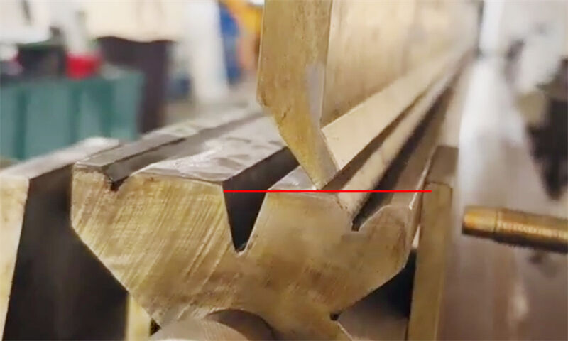
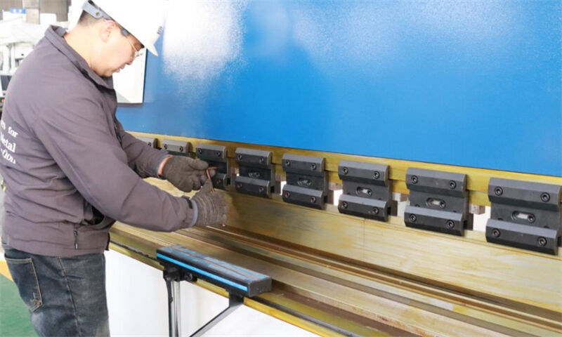
Use a centerline marking tool (such as a laser centering instrument or a mechanical centering rod) to align the V-grooves or cutting edges of the upper and lower molds.
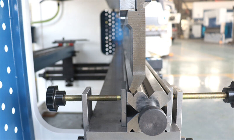
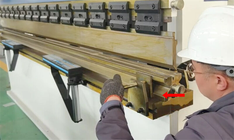
Adjust the lateral position of the mold holder, and control the error within ±0.5mm.
2. Fine-tune parallelism
Inching operation, let the upper knife slowly move down until it touches the upper plane of the mold, and slightly pressurize (be careful not to pressurize for a long time, the pressure should be less than 12Mpa). Then return.
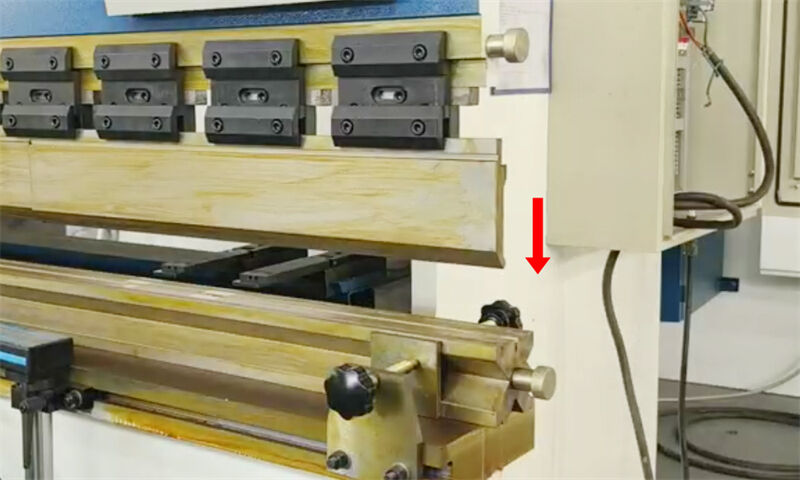
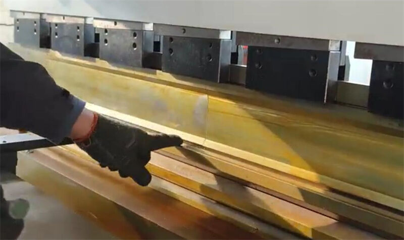
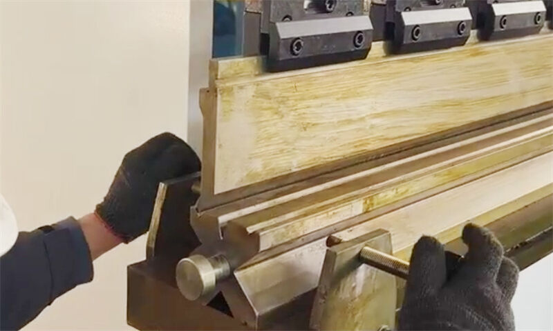
Adjust the lower mold to move to the V8 or V12 slot to complete the centering of the upper and lower molds.

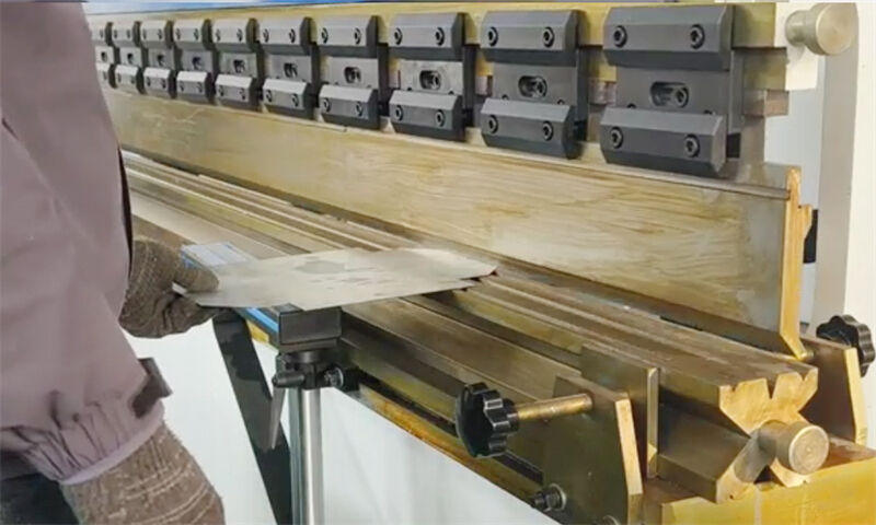
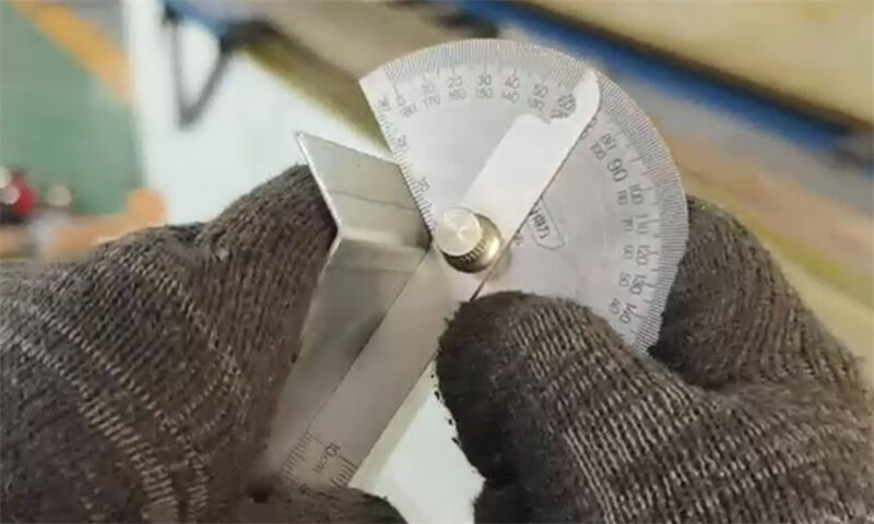
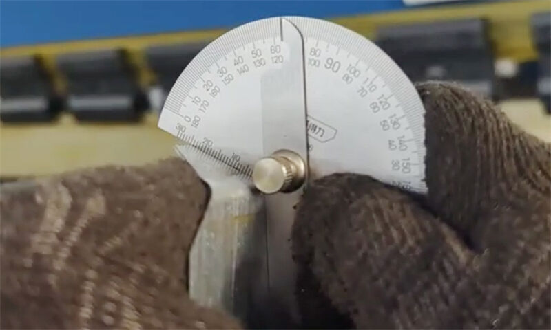
Single-side angle test, use two pieces of material to bend and test on both sides of the machine tool at the same time, and compare the angles on both sides (note that the test angle must be greater than 90°, and full pressure must be applied when bending).
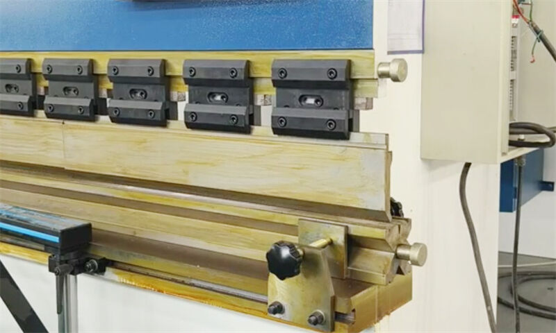
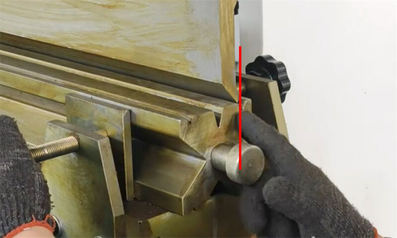
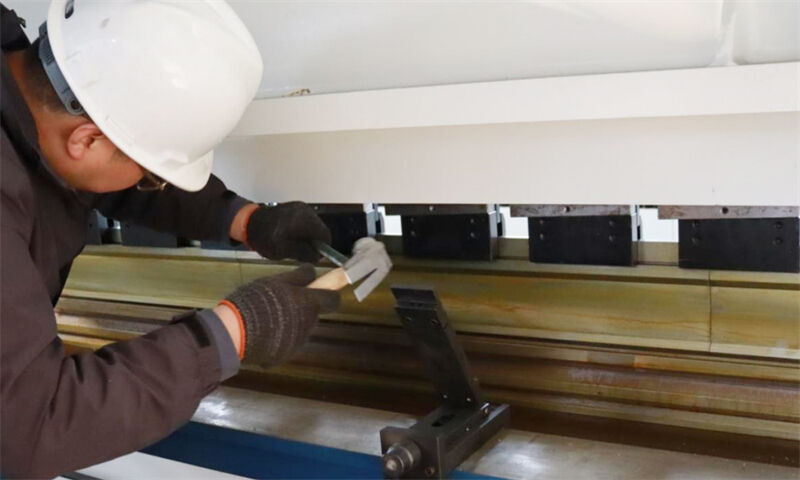
Completely eliminate the gap between the mold clamps. Adjust the position of the lower mold to ensure that the tip of the upper mold is pressed on the upper plane of the lower mold. Inching operation, let the upper knife slowly move down until it touches the upper plane of the mold, and slightly pressurize (be careful not to pressurize for a long time, the pressure is about 12Mpa). Loosen the bevel iron fixing screw, and then knock the bevel iron (use a copper rod to knock) to ensure that there is no gap between the upper and lower molds.
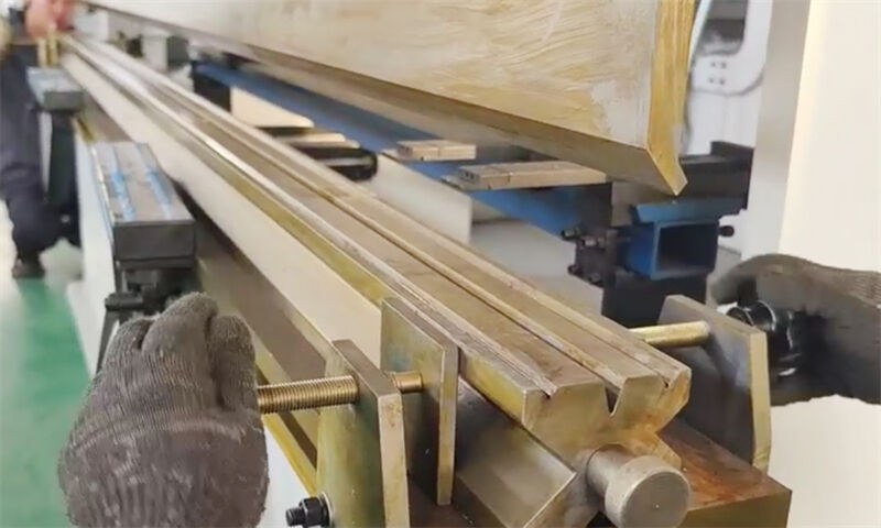
3. Lock parameters
After completing the adjustment, tighten all fixing bolts and mark them with anti-loosening marks.
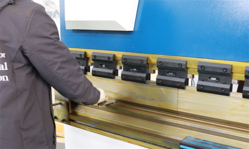
Use a feeler gauge to check the mold gap after closing to ensure that there is no local overtightening or gaps.
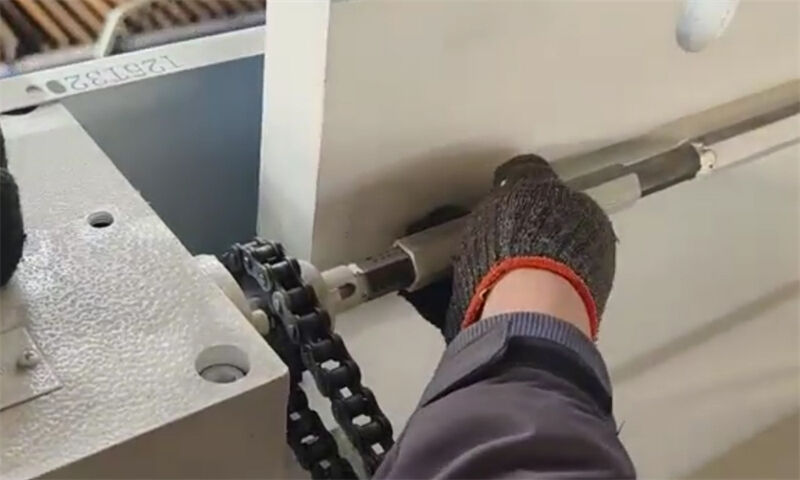
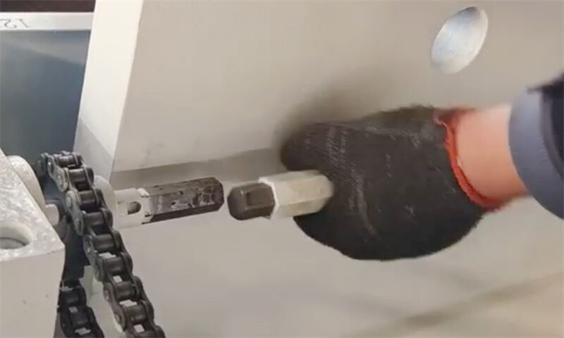
Move the lower die, select the normal bending notch, and test normally. If there is still a certain error in the left and right angles, manually adjust the synchronous shaft at the rear of the cylinder.
4. Precautions
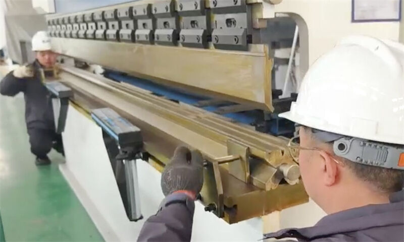
Safe operation: Be sure to turn off the power before adjustment, and wear protective gloves and goggles.
Tool selection: High-precision measuring tools (such as micrometers, laser detectors) are preferred.
Step-by-step verification: Each step of adjustment must be verified by trial folding to avoid cumulative errors.
Equipment differences: Different models of bending machines may use mechanical/hydraulic compensation methods, which require adjustment in accordance with the equipment manual.
Through the system adjustment of the above steps, the bending accuracy (angle error ≤ 0.5°) and mold service life can be significantly improved, and material waste and equipment loss can be reduced. In actual operation, it is necessary to respond flexibly based on experience, for example, for thick plates or high-strength materials, the pressure compensation amount needs to be appropriately increased.

