


Three Approaches to Expandable Sheet Metal Surface Deployment
In this article, I’ll explore three ways to unfold expandable sheet metal surfaces. Mastering unfolding techniques such as parallel line unfolding, radial line unfolding, and triangular unfolding is crucial for professionals in the sheet metal industry, as it enables them to design and manufacture components with greater efficiency and precision. Whether you’re a seasoned professional or just starting out, mastering surface treatment techniques such as phosphating, metal drawing, and laser texturing can significantly enhance your workflow and product quality, as demonstrated by innovations in metal manufacturing and the broad applications of these techniques across industries. Join me as I delve into each method, discussing their advantages and practical applications in the industry.
Despite their complex and varied shapes, sheet metal components are primarily composed of basic geometric shapes and their combinations. Basic geometric shapes can be divided into two major categories: planar and curved surface types. Common planar three-dimensional shapes (mainly including quadrilateral prisms, truncated prisms, oblique parallel planes, quadrilateral pyramids, etc.) and their planar combinations are shown in Figure (a), while common curved three-dimensional shapes (mainly including cylinders, spheres, right circular cones, oblique cones, etc.)heir curved assemblies are shown in figure (b) below. The basic curved three-dimensional sheet metal components depicted in (b) reveal a rotating body, created by a bus bar (either straight or curved, indicated by a plain line) revolving around a stationary axis. The surface on the outside of the rotating body is called the rotating surface. Cylinders, spheres and cones are all rotating bodies and their surfaces are rotating surfaces, whereas oblique cones and irregularly curved bodies are not rotating bodies. A cylinder is formed by a straight line, known as the axis, rotating around another straight line that remains parallel and equidistant to it. This results in a three-dimensional shape with two circular bases and a curved surface connecting them. A cone is a three-dimensional geometric shape formed by rotating a right triangle around one of its legs, which acts as the axis of rotation. A sphere is formed by rotating asemi-circular arc around its diameter.
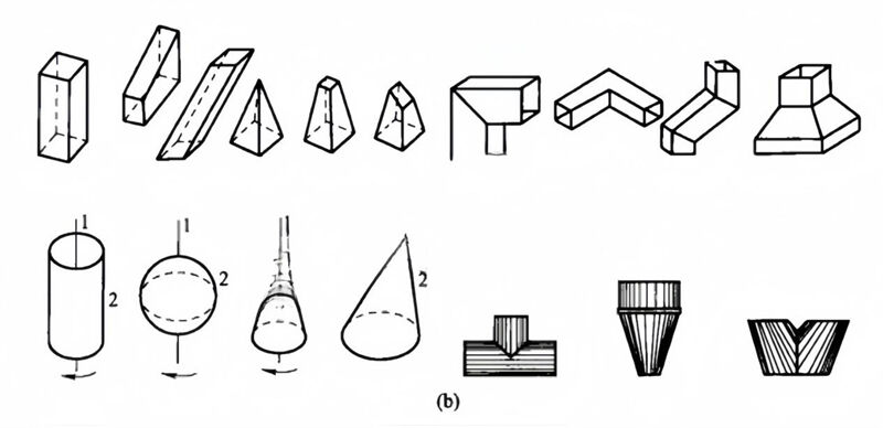
There are two types of surface: expandable and non-expandable. To check if a surface or part of it is spreading, place a ruler against the object, turn it, and observe if it fits smoothly along the surface in one direction. If it does, mark the position and select a new spot nearby. The surface of the measured part of the object is extensible. In other words, any surface where two adjacent lines can form a plane (i.e. where two lines are parallel or intersect) is expandable. This type of surface includes the plane, column surface, and cone surface, among others, which are scalable. However, surfaces where the generating line is a curve or where two adjacent lines form the intersection of the surface, such as the sphere, ring, spiral surface, and other irregular surfaces, are not scalable. For non-expandable surfaces, only approximate expansion is possible.
There exist three primary techniques for unfolding expandable surfaces: the parallel line method, the radial line method, and the triangle method. Below is an outline of the unfolding procedures.
Parallel line method
By slicing the prism or cylinder along parallel lines, the surface is divided into quadrilaterals which are then unfolded sequentially to form an expanded map. This technique is known as the parallel line method. The principle behind the parallel line method lies in the fact that the surface consists of a series of parallel lines. When adjacent lines and the areas enclosed by them (at their upper and lower ends) are considered, they serve as approximations A plane trapezoid (or rectangle), divided into infinite tiny areas, sums up to the surface area of the shape. When all these tiny areas are unfolded in their original order and relative positions, without omission or overlap, they form the surface of the truncated body. Of course, dividing the surface of a truncated body into an infinite number of small planes is impossible.s, but it is possible to divide it into dozens or even several small planes.
Any geometry where the cords or prisms are parallel to each other, such as rectangular tubes, round tubes, etc., can be surface unfolded by the parallel line method. The diagram below shows the unfolding of the prismatic surface.
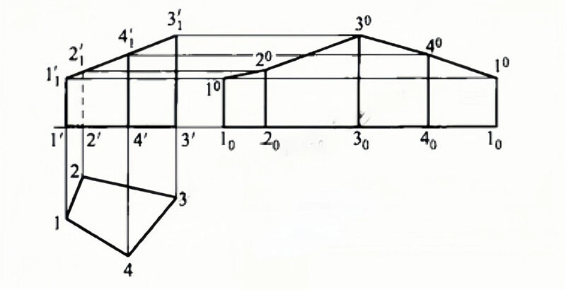
The steps to make an unfolding diagram are as follows.
1. to make the main view and top view.
2. make the base line of the unfolding diagram, i.e. the extension line of 1′-4′ in the main view.
3. record the perpendicular distances 1-2, 2-3, 3-4, 4-1 from the top view and move them to the datum line to obtain points 10, 20, 30, 40, 10 and draw perpendicular lines through these points.
4. drawing parallel lines to the right from points 1′, 21′, 31′ and 41′ in the main view, intersecting the corresponding perpendiculars to give points 10, 20, 30, 40 and 10
5. Connect the points with straight lines to obtain the unfolding diagram.
The diagram below shows
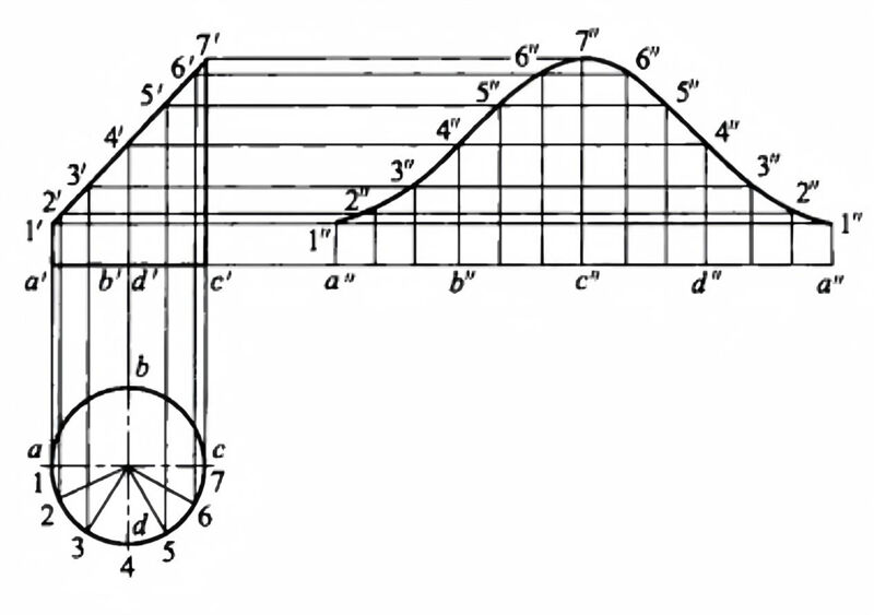
The unfolding of a diagonally cut cylinder.
The steps to make an unfolding diagram are as follows.
1. make the main view and top view of the oblique truncated cylinder.
2. Divide the horizontal projection into a number of equal parts, here into 12 equal parts, the half circle is 6 equal parts, from each equal point up to the vertical line, in the main view of the corresponding line, and cross the oblique section circumference at 1′, … , 7′ points. The points of the circle are the same.
3. Expand the cylindrical base circle into a straight line (the length of which can be calculated using πD) and use it as a reference line.
4. Draw a vertical line from the equidistant point upwards, i.e. the plain line on the surface of the cylinder.
5. Draw parallel lines from the main view at 1′, 2′, … , 7′ respectively, and intersect the corresponding prime lines at 1″, 2″, … The endpoints of the lines on the unfolded surface.
6. Connect the endpoints of all the plain lines into a smooth curve to obtain a diagonal cut of the cylinder 1/2. The other half of the unfolding is drawn in the same way to obtain the desired unfolding.
From this, it is clear that the parallel line method of expansion has the following characteristics.
1. The parallel line method can only be applied if the straight lines on the surface of the form are parallel to each other and if the real lengths are shown on the projection diagram.
2. The specific steps for performing entity expansion using the parallel line method are as follows: First, divide equally (or arbitrarily) in the top view, then draw perpendicular lines from each division point to the projection line in the main view, obtaining a series of intersection points in the main view (these points actually divide the surface of the shape into multiple small parts); Next, cut line segments in the direction perpendicular to the (main view) straight line, making them equal to the cross-sectional (perimeter), and mark them in the top view.nts, over this line segment The vertical line of this line is drawn through the points on the line and the vertical line of the line drawn from the intersection point in the first step of the main view, and then the intersection points are connected in turn (this is actually a number of small parts divided by the first step in order to spread out), then the unfolding diagram can be obtained.
On the surface of the cone, there are clusters of lines or prisms, which are concentrated at the apex of the cone. Utilizing the apex and the radiating lines or prisms, the expansion method is drawn, a technique known as the radiometric method, which is widely applied in the field of mineral exploration.
Radial method of unfolding the principle is:Consider any two adjacent lines and their baseline as an approximate small plane triangle. When the base of this small triangle approaches zero infinitely, that is, when there are infinitely many small triangles, the sum of the areas of these small triangles equals the area of the original cross-section. and when all small triangles are not missing, not overlapping, not creased according to the original left and right relative order and position When all the small triangles are laid out in their original relative order and position, the surface of the original form is also expanded.
The radial method is used to unfold the surfaces of various cones, including orthocones, oblique cones, and prisms, provided they share a common cone top. The diagram below shows the unfolding of the oblique truncation of the top of a cone.
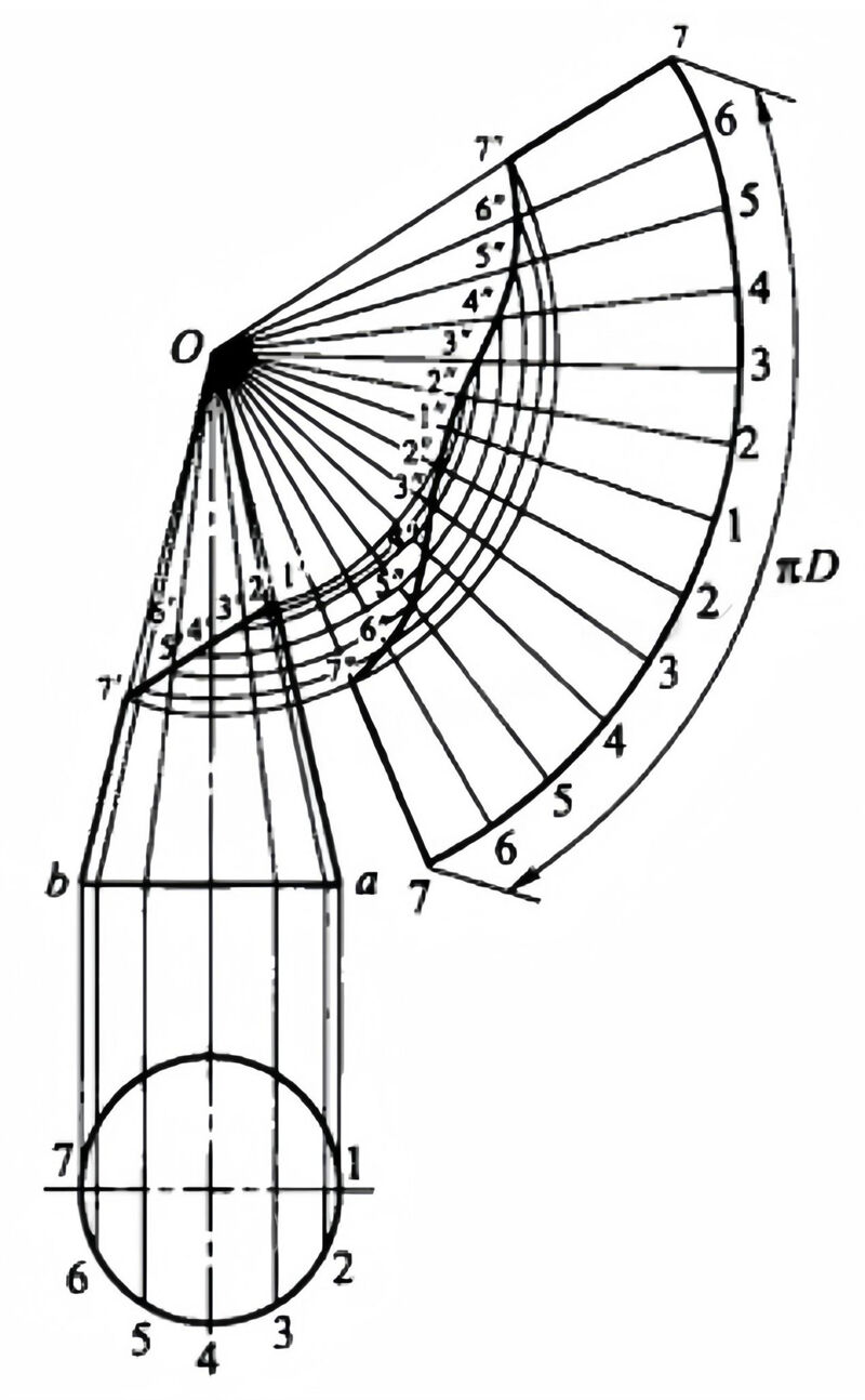
The steps to make an unfolding diagram are as follows.
1. Draw the main view and fill in the top truncation to form a complete cone.
2. Make a cone surface line by dividing the base circle into a number of equal parts, in this case 12 equal parts, to obtain 1, 2, …, 7 points, from these points to draw a vertical line upwards, and intersect the base circle orthographic projection line, and then connect the intersection point with the top of the cone O, and intersect the oblique surface at 1′, 2′, …, 7′ points. The lines 2′, 3′, …, 6′ are not real lengths.
3. Draw a sector with O as the centre and Oa as the radius. The length of the arc of a sector is equivalent to the circumference of its base circle. Divide the sector into 12 equal parts, intercepting equal points 1, 2, …, 7. The arc lengths of the equal points are equal to the arc lengths of the circumference of the base circle. Using O as the centre of the circle, make leads (radial lines) to each of the equal points.
4. From the points 2′, 3′,…, 7′ make leads parallel to ab, intersecting Oa, i.e. O2′, O3′,… O7′ are the real lengths.
5. Using O as the centre of the circle and the perpendicular distance from O to each of the intersection points of Oa as the radius of the arc, intersect the corresponding prime lines of O1, O2, …, O7, to obtain the points of intersection 1”, 2”, …, 7”.
6. Connect the points with a smooth curve to obtain a diagonal intercept of the top of the conical tube. The radiometric method is a very important method of expansion and is applicable to all cone and cone truncated components. Although the cone or truncated body is unfolded in a variety of ways, the unfolding method is similar and can be summarised as follows.
In an alternative perspective, the cone's entirety is enlarged by elongating its edges (prisms) and fulfilling other formal requirements, albeit this procedure is unnecessary for truncated bodies possessing vertices.
By equally dividing the perimeter of the top view (or, optionally, dividing it arbitrarily), lines are drawn across the cone's apex, encompassing lines over the vertices of lateral ribs and prism sides, corresponding to each division point, ultimately segmenting the cone's or truncated body's surface into smaller sections.
By applying the method of finding the real lengths (the rotation method is commonly used), all the lines that do not reflect the real lengths, the prisms, and the lines associated with the expansion diagram are found without missing the real lengths.
Using the real lengths as a guide, the entire side surface of the cone is drawn, together with all the radiating lines.
On the basis of the whole cone side surface, draw the truncated body on the basis of the real lengths.
Triangulation method
If there are no parallel lines or prisms on the surface of the part, and if there is no cone top where all the lines or prisms intersect at one point, the triangle method can be used. The triangle method is applicable to any geometry.
The triangle method involves dividing the surface of the part into one or more groups of triangles. Each triangle's side lengths are then measured accurately. Following specific rules, these triangles are flattened onto a plane and unfolded. This technique for creating unfolded diagrams is known as the triangle method. Although the radial method also divides the surface of a sheet metal product into a number of triangles, the main difference betweeThe difference between this method and the triangular method lies in how the triangles are arranged. The radial method is a series of triangles arranged in a sector around a common centre (cone top) to make an unfolding diagram, whereas the triangular method divides the triangles according to the surface shape characteristics of the sheet metal product, and these triangles are not necessarily arranged around a common centre, but in many cases are arranged in a W-shape. In addition, the radial method is only applicable to cones, whereas the triangular method can be applied to any shape.
Although applicable to any shape, the triangle method is only used when necessary due to its tedium. For instance, when the surface lacks parallel lines or prisms, the parallel line method cannot be used for expansion, and when lines or prisms do not converge at a vertex, the radial method is inapplicable. In such cases, the triangle method is employed for surface expansion. The diagram below shows the unfolding of a convex pentagram.
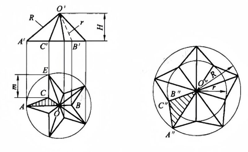
The steps of the triangle method for the expansion diagram are as follows.
1. Draw a top view of the convex pentagram using the method of a positive pentagon within a circle.
2. Draw the main view of the convex pentagram. In the diagram, O’A’ and O’B’ are the real lengths of the OA and OB lines, and CE is the real length of the bottom edge of the convex pentagram.
3. Use O’A’ as the major radius R and O’B’ as the minor radius r to make the concentric circles of the diagram.
4. Measure the lengths of the circles in order of m 10 times on the major and minor arcs to obtain 10 intersections of A”… and B”… on the major and minor circles respectively.
5. Connect these 10 points of intersection, resulting in 10 small triangles (e.g. △A “O “C” in the diagram), which is the expansion of the convex pentagram.
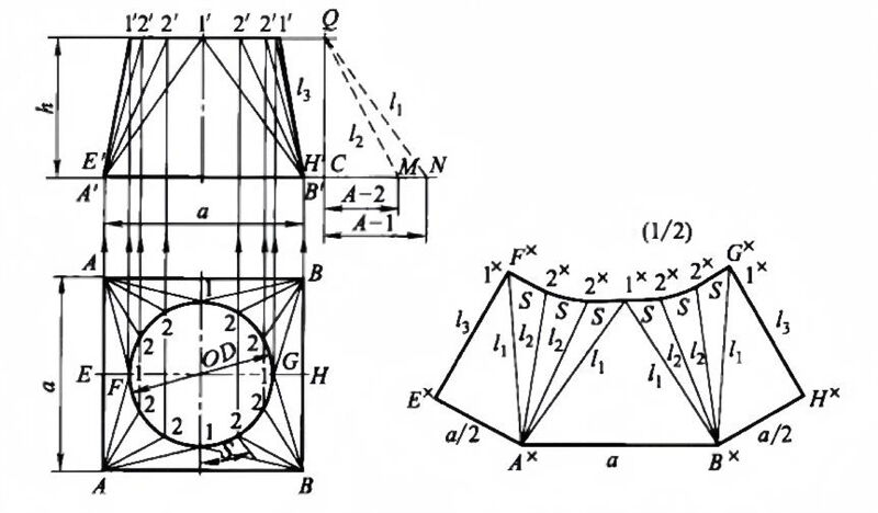
The ‘sky is round’ component shown below can be seen as a combination of the surfaces of four cones and four flat triangles. If you apply the parallel line method or the radial line method, it is possible, but it is more troublesome to do so.
The steps of the triangle method are as follows.
1. The plan will be divided into 12 equal parts along its circumference. Points will be marked at intervals corresponding to 1, 2, 2, 1, and similar angles, connecting points A or B. Vertical lines will then be drawn from these points to intersect the main view at the upper edge, marked as 1′, 2′, 2′, 1′. These points will then be connected to A’ or B’. The significance of this step is that the side surface of the sky is divided into a number of small triangles, in this case into sixteen small triangles.
2. From the symmetrical relationship between the front and back of the two views, the lower right corner of the plan 1/4, the same as the remaining three parts, the upper and lower ports in the plan reflect the real shape and real length, because GH is the horizontal line, and thus the corresponding line projection 1’H’ in the main view reflects the real length; while B1, B2 but in any projection map does not reflect the real length, which must be applied to find the real length of the line method to find the real length, here The right triangle method is used (note: A1 equals B1, A2 equals B2). Adjacent to the main view, two right-angled triangles are constructed such that one of the perpendicular sides, CQ, is equal to 'h', and the hypotenuses, A2 and A1, correspond to the lines QM and QN, representing their actual lengths. This configuration allows for the application of the Pythagorean theorem, which states that in a right-angled triangle, the square of the length of the hypotenuse (c) is equal to the sum of the squares of the lengths of the other two sides (a and b), expressed as c² = a² + b². The significance of this step is to find out the length of all the small triangle sides, and then analyse whether the projection of each side reflects the real length, if not, then the real length must be found one by one using the real length method.
3. Draw the development diagram. Make the line segment AxBx equal to a, where Ax and Bx are the centers of the circle, and the actual length of the line segment QN (i.e., l1) as the radius of the arc intersecting with 1x, thus forming the plane diagram of the small triangle △AB1; with 1x as the center, draw an arc using the length of the arc S as the radius, and then with Ax as the center, use the actual length of the line segment QM (i.e., l2) as the radius of the arc intersecting with 2x, thus completing the drawing of the development diagram. e diagram of the small triangle △A12 This gives the expansion of the triangle ΔA12 in the plan. Ex is obtained by intersecting an arc drawn with Ax as the centre and a/2 as the radius, and an arc drawn with 1x as the centre and 1’B’ (i.e. l3) as the radius. Only half of the full spread is shown in the spread diagram.
The significance of choosing FE as the seam in this example is that all the small triangles divided on the surface of the form (truncated body) are laid out on the same plane, in their actual size, without interruption, omission, overlap or crease, in their original left and right adjacent positions, thus unfolding the entire surface of the form (truncated body).
From this, it is clear that the triangular method of unfolding omits the relationship between the original two plain lines of the form (parallel, intersecting, dissimilar) and replaces it with a new triangular relationship, thus it is an approximate method of unfolding.
1. Correctly dividing the sheet metal component's surface into small triangles is crucial for the triangle unfolding method. Generally, the division should meet four conditions to be considered correct; otherwise, it is wrong: all vertices of the triangles must lie on the component's upper and lower edges, and the triangles must not cross the component's internal space.t can only be attached to the All two adjacent minor triangles have and can have only one common side; two minor triangles separated by one minor triangle can have only one common vertex; two minor triangles separated by two or more minor triangles either have a common vertex or no common vertex.
2. Inspect all the sides of the small triangles to determine which sides reflect the true length and which do not. For sides that do not reflect the true length, the true lengths need to be determined one by one according to the method of finding them.
3. Based on the adjacent positions of the small triangles in the figure, draw all the small triangles in sequence, using known or already calculated true lengths as radii. Finally, connect all the intersection points with curves or dashed lines according to the specific shape of the component to obtain the developed view.
Comparison of the three methods
The triangle unfolding method can apply to all expandable forms, whereas the radial method is limited to unfolding intersections of lines at a composition point, and the parallel line method is confined to unfolding elements parallel to each other's components. Both the radial and parallel methods can be considered special cases of the triangle method, as the triangle method involves more cumbersome steps in terms of drawing simplicity. GenGenerally speaking, the three methods of unfolding are selected based on the following conditions.
1. If the component of a plane or surface, regardless of whether its cross-section is closed, projects lines onto a surface that are all parallel to one another's solid long lines, and on another projection surface, only a straight line or curve is projected, then the parallel line method can be applied for unfolding.
2. If a cone (or part of a cone) is projected on a projection plane, its axis reflects the real length, and the base of the cone is perpendicular to the projection plane, then the most favorable conditions for applying the radiometric method are met ('most favorable conditions' does not imply necessity, as the radiometric method involves a real length step, enabling the identification of all necessary elements regardless of the cone's projection position)ts line real length, and then expand the side of the cone).
3. When a plane or a surface of a component is polygonal in all three views, that is, when a plane or a surface is neither parallel nor perpendicular to any projection, the triangle method is applied. The triangle method is particularly effective when drawing irregular shapes.
About Gary Olson
As a dedicated author and editor for JUGAO CNC, I specialize in crafting insightful and practical content specifically designed for the metalworking industry. With years of experience in technical writing, I focus on providing in-depth articles and tutorials that help manufacturers, engineers, and professionals stay informed about the latest innovations in sheet metal processing, including CNC press brakes, hydraulic presses, shearing machines, and more.

